When you’re designing plastic parts that need tight tolerances, whether for medical, aerospace, or high-end electronics, standard injection molding rules no longer apply. You’re dealing with tolerances in the hundredths of a millimeter, where even a small warp, sink mark, or draft error can make a part unusable.
In this guide, you’ll learn what separates a good part design from a precision-ready one. We’ll break down specific design tips, materials advice, and pitfalls that most engineers only learn after a failed production run. If you want to avoid costly rework or rejected parts, read on.
Understanding the Precision Context
When you hear “high precision injection molding,” it’s not just marketing—it’s about hitting tolerances in the range of ±0.01 mm or better. That level of control isn’t needed for every project, but when your parts interact with tight-fitting assemblies, optical devices, or fluid systems, it becomes critical.
The key is knowing whether your application demands precision or whether you’re over-engineering. Many parts function perfectly with ±0.1 mm tolerances. But in aerospace, medical, or electronics, even a small deviation can affect sealing, alignment, or signal performance.
Before diving into design or tooling, ask yourself:
- What’s the functional role of each dimension?
- Will this part mate with metal or other plastics?
- Are there temperature or moisture variations in the final use?
Precision starts with clarity. The more you define what actually needs tight control, the less risk you take on later.
Designing with Precision in Mind: Practical Tips that Make a Difference
Getting precision right in injection molding isn’t just about the mold or the machine—it starts with how you design the part. If your CAD model ignores how plastic flows, cools, and shrinks, no amount of fine-tuning later can make up for it. Below are proven, engineering-backed design tips that help you hit tight tolerances and avoid downstream surprises.
1. Keep Wall Thickness Uniform
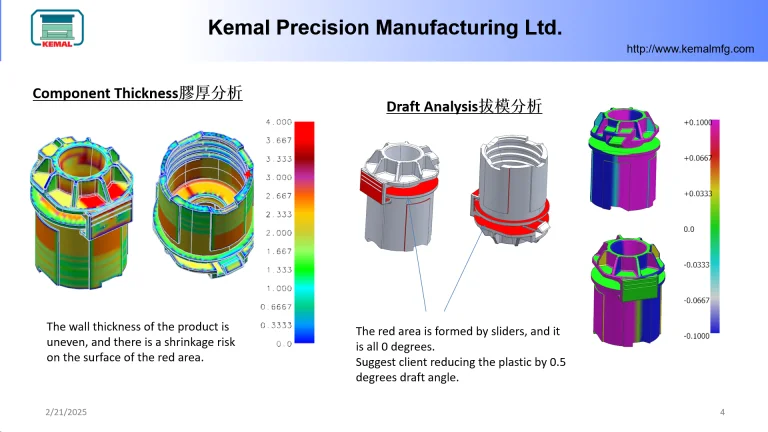
One of the most overlooked sources of variation is inconsistent wall thickness. Thicker sections cool slower than thinner ones, causing internal stress, shrinkage differences, and warping. These issues can throw off your most critical dimensions. Aim for a uniform wall, and when transitions are needed, taper them gradually—never abruptly.
2. Round Corners, Especially at Transitions
Sharp internal corners act like stress amplifiers. They not only increase the risk of cracking but also affect how molten plastic fills the cavity. Use generous fillets at intersections—both for better flow and dimensional stability. As a rule, the internal radius should be at least 0.5× the wall thickness.
3. Draft Thoughtfully—But Don’t Compromise Critical Fits
Adding 1–2 degrees of draft per side is standard for easy ejection, but too much draft in precision areas can distort fit-critical geometry. The solution? Add draft where it doesn’t interfere with function, and keep critical sections—like holes or mating surfaces—on lifters or shut-offs with controlled geometry.
4. Avoid Tiny or Fragile Features Unless Necessary
Super thin ribs, micro-textures, or ultra-fine snap fits might look good in CAD, but they’re often the first to fail in molding. If a feature doesn’t serve a structural or alignment function, reconsider it. And if it must stay, reinforce it with ribs or adjust gate placement to ensure clean fill.
5. Design for Balance—Geometrically and Thermally
Asymmetry in your part, such as a large boss on one side or uneven mass distribution, can lead to unpredictable shrinkage and warping. This is especially problematic in multi-cavity molds. Aim for balance, not just in shape but in thermal behavior: mirror features when you can, and place cooling channels accordingly.
6. Protect Fit-Critical Areas with Functional Design Aids
Tight tolerance holes, shafts, or seal surfaces deserve special treatment. Add alignment bosses, lead-ins, or sacrificial locator features that allow the mold to register consistently. Also, define clear datums in your 2D drawings to guide the mold builder and QC inspection.
Where Precision Fails: Design Mistakes You Can’t Afford to Make
Even if you choose the best mold maker and material, design flaws can still wreck your precision goals. In fact, many dimensional issues aren’t due to poor tooling—they’re baked into the part from the start. Here are the most common mistakes that quietly sabotage your accuracy, and how you can avoid them.
1. Ignoring Material Shrinkage in CAD
Every plastic shrinks as it cools—some more than others. If you don’t account for this during the design stage, your finished parts will be undersized or warped, even if the mold is perfect. Always reference the actual shrink rate of the resin you’re using, and coordinate with your tooling engineer to apply offsets during mold design.
Example: Designing a 10 mm boss for a high-shrink PP material without compensation can easily result in a 9.7 mm actual size, out of spec.
2. Overusing Thick or Uneven Walls
Wall thickness isn’t just about structural strength—it heavily influences how evenly the part cools. Overly thick zones tend to shrink more and cool slower, leading to localized warping or sink marks. Worse, uneven walls introduce internal stress that distorts precise features.
Tip: Stay within 1.5–3 mm for most engineering plastics, and avoid thickness jumps of more than 30% without a gradual transition.
3. Skipping Moldflow Simulation
If you don’t simulate how the material flows through your part, you’re guessing. Moldflow analysis helps you predict weld lines, air traps, pressure drops, and cooling inefficiencies—all of which affect dimensional stability. Not running a simulation is like flying blind.
What can go wrong? A poorly placed gate may cause jetting or asymmetrical fill, leading to warped flat surfaces or deformed holes.
4. Tolerance Overkill
You may think tight tolerances = better quality, but that’s not always true. Applying ±0.02 mm everywhere will drive up machining cost, increase QC rejects, and may not even be manufacturable. Focus precision only where it affects fit or function.
Practical rule: Limit your tightest tolerances to mating parts, seal zones, and datum-based interfaces. Let cosmetic or non-critical areas breathe.
5. Disregarding Flow Orientation
The direction in which plastic flows affects how it shrinks and warps. Long, unsupported features aligned against the flow direction tend to curl or twist. If you ignore this, your flat surfaces may turn into potato chips after molding.
Good practice: Align ribs and long features with flow lines when possible. If unavoidable, add bracing or split the part strategically.
Don’t Wait—Involve Your Mold Designer from Day One
Precision doesn’t happen in isolation. It’s not just about your CAD model or your tolerance stack-up. If you’re serious about hitting tight specs, you need to loop in your mold designer early—ideally before you even lock your 3D file.
Why DFM Isn’t Optional for Precision Parts
Design for Manufacturability (DFM) is more than a checklist—it’s how you bridge the gap between design intent and real-world injection molding. A seasoned mold designer will flag features that may cause sink marks, warping, or ejection issues before you invest time and money in tooling.
For high-precision parts, even minor design missteps—like a poorly placed gate or an uneven parting line—can throw off critical dimensions.
What Early Collaboration Actually Looks Like
Here’s how a typical early-stage partnership unfolds when done right:
- Step 1: You share 3D CAD and part requirements (fit, function, tolerance zones).
- Step 2: The mold designer runs mold flow analysis to predict fill patterns, cooling behavior, and shrinkage direction.
- Step 3: You get practical feedback—like shifting the gate to reduce pressure drop, or adjusting draft angles to aid clean ejection without warping.
- Step 4: You iterate—slightly modifying wall thickness or moving parting lines to align with precision zones.
Each change might look small, but it compounds into significantly better outcomes in terms of stability, repeatability, and dimensional accuracy.
A Real Example: Minor Gate Change, Major Improvement
One aerospace client we worked with had a cylindrical housing requiring ±0.02 mm roundness. Their original design gated from the side. Simulation showed asymmetric fill, causing ovality.
By simply shifting the gate to a central location and adjusting the vent layout, we cut warpage by 60% and avoided expensive post-machining.
Choose Your Resin and Tolerances with Intent, Not Assumptions
When you’re targeting tight tolerances in plastic injection molding, material selection isn’t just a sourcing decision—it’s a dimensional control strategy. Every resin behaves differently once injected: some flow fast but shrink unevenly, others hold dimensions but resist filling complex features.
Not All Resins Shrink the Same Way
Take acetal (POM), polycarbonate (PC), and liquid crystal polymer (LCP)—three common high-performance materials:
- POM has excellent machinability but high and directional shrinkage. Without proper mold compensation, your parts will be off.
- PC is dimensionally stable but slower to fill, which affects thin walls and long flow paths.
- LCP flows like water and shrinks minimally, ideal for micro parts, but it’s sensitive to gate location and weld lines.
That means before locking in tolerances, you need to understand how your chosen resin will behave in the mold. Mold flow analysis helps—but only if the material data is accurate.
Don’t Just Apply ±0.01 mm Everywhere
One of the most common pitfalls in precision molding is over-specifying tolerances. Yes, some features may need ±0.01 mm—but not every dimension does. Tight specs across the board will:
- Increase tooling cost
- Lengthen mold development cycles
- Complicate process validation
Instead, focus your tightest tolerances on critical-to-function zones: press fits, alignment points, optical interfaces, etc.
Use GD&T—Not Just Linear Callouts
If you’re still calling out every dimension with a simple ±0.05 mm note, you’re leaving room for ambiguity. For precision plastic parts, GD&T (Geometric Dimensioning and Tolerancing) is a more effective tool. It helps define:
- True position for holes
- Flatness for mating faces
- Profile control for complex contours
More importantly, it communicates how much variation your part can tolerate functionally, not just geometrically.
The Key: Align Material Behavior with Functional Need
Precision starts when your material properties, design goals, and manufacturing method work in sync. A part requiring tight concentricity across multiple diameters may need a resin with low anisotropic shrinkage. A part meant to flex slightly under load? You’ll need to relax your tolerances accordingly.
Early planning here saves downstream firefighting. And it gives your mold maker the context to dial in process parameters that actually hit your target consistently.
Validate Early, Adjust Wisely: The Role of Prototyping in Precision Molding
When you’re chasing microns in part tolerance, guessing isn’t an option. Before committing to steel, you need real-world feedback—and that’s where rapid prototyping becomes essential.
Why You Can’t Skip Pre-Tooling Prototypes
A CAD model tells you how a part should behave. But only a physical prototype reveals how it actually behaves once it’s built. In high-precision injection molding, this gap is critical.
Using CNC-machined plastic samples or micro-injection prototypes lets you:
- Validate key dimensions early without full tooling
- Identify issues like warpage, material sink, or tolerance stacking
- Test form, fit, and function in mating assemblies
Even if your production process will be injection molding, early prototypes help you spot and solve problems before you’re locked into a mold design.
Prototype → Learn → Adjust
Let’s say your part requires a ±0.02 mm fit with a metal insert. A CNC prototype may already show you the fit is too tight under thermal stress. Instead of finding this after T1, you can tweak the design—maybe add a relief, change a radius, or adjust the insert tolerance—before cutting steel.
This early feedback loop saves time and reduces risk.
Compare Sample vs. Final Molded Part
When you move from prototype to production, don’t throw away that early sample. Use it as a reference point:
- How does material shrinkage affect final dimensions?
- Are surface features or edges consistent across versions?
- Do the functional tolerances hold up under real injection conditions?
Comparing prototype and molded part side-by-side gives you insight into how your resin, geometry, and mold interact—something simulation alone can’t fully predict.
Final Recap and What You Should Do Next
Designing for high precision injection molding isn’t just about drafting a part that looks right. It’s about understanding how your design interacts with material behavior, tooling constraints, and the molding process itself. Precision is earned—not assumed.
To apply what you’ve learned, here’s a short checklist you can use for your next precision molding project:
- Involve your mold supplier during the design phase, not after
- Perform mold flow analysis to anticipate filling and cooling behavior
- Set clear, prioritized tolerances—don’t over-specify everything
- Limit wall thickness variation to reduce internal stress
- Confirm gate locations and cooling strategy early
- Use prototypes to test assemblies, fits, and functional features
Precision injection molding is unforgiving. But if you design with intent, collaborate early, and validate smartly, it becomes a powerful tool in your product development process.

 By
By
 By
By
 By
By

 By
By